Module Icons and Port Colors
Module Icons
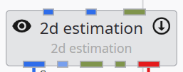
Modules which include "Run" control and/or connect to the viewer have special icons on the module face which allow you to quickly control visibility and execution. Below is 2d estimation with its default options:
Visible and Run: The eyeball icon on the left shows that the renderable object's visibility is Visible and the down-arrow on the right shows that the Allow Run toggle is set to Run (data will pass through or out of this module).
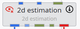
Hidden and Off: Below we are showing the object's visibility set to Hidden and the Allow Run toggle is set to Off.

There are two other options for the visibility icon:
Excluded is a special option that will exclude this module's output to exports for web viewing (CTWS) or PDF creation. For CTWS, it is equivalent to disconnecting the module from the viewer in EVS. In EVS it is equivalent to Hidden.
Locked is a special option that forces the module's visibility to always be Visible in a web export (CTWS). This is useful for company logos and/or content that you wish to always have visible.

Parent/Child Visibility Options: Objects which contain multiple child renderable connections, such as the sequence modules or group objects, behave differently in terms of visibility. Their Visibility is based on the modules connected to their input red port. Setting their visibility automatically attempts to set the visibility of all objects connected to them.
Since they can have children attached in with different visibilities, they have three additional possible Visibility options:
1. If some children are Visible and some are Hidden, the module will be set to Indeterminate:

2. If the module is Visible, but there is one or more children that are Excluded, the module will be set to Visible with Excluded Child:

3. If the module is Hidden, but there is one or more Locked children, the module will be set to Hidden with Locked Child:

Module Port Colors
- Renderable object
 This commonly used port connects various modules generally to the viewer. It contains the grids, data and rendering information.
 - Field
 This is the most common port which passes your grids and data (nodal or cell) between modules that create these fields and those that subset or modify them.
 - Realization Field This is the
- String
 Used to pass strings which can range from single words to phrases and file names and paths.
 - Geologic Legend Information
 This data port contains material names from geology modules
 - Vistas Data
 Used to pass geologic surface information to Groundwater Vistas to initialize MODFLOW models.
 - Number
 This port passes a real number. format_string has number input ports
- Side port: Z-Scale
 This port passes the z-exaggeration factor. Used by many modules such as explode_and_scale.
 - Side port: Explode Factor This port passes the explode factor. Used by many modules such as explode_and_scale.
- Side port: Z-Scale
- Date-Time
 This port passes date & time
 - View:
 This port is a viewer output port and input to a few modules which export your entire viewer contents.
When trying to determine which port on the module icon corresponds to which documented item, remember:
- Input Ports are documented left side top to bottom and the top side from left to right.
- Output ports are documented rights side top to bottom and the bottom side from left to right.
With the cursor on the module, hover over a port for details or click the right mouse button to activate the menu.
PORT SUBTYPES:
In addition to the primary colors of ports, some ports have subtypes designated by one or more small colored circular dots. These dots designate port subtypes which will further restrict how ports connect based on the type of data that the ports contain. The port subtypes depend on the types of ports and are in three primary classes:
- Fields
- Geology: Goldenrod
- Structured: LightSalmon
- Uniform: Purple
- Node Data: LightBlue
- Cell Data: Green
- Number
- Z Scale: Pink
- Explode: Gold
- String
- Filename: Blue
- Analytical File: GreenYellow
- Stratigraphy File: LightGoldenrodYellow
- Lithology File: DarkGray
Below is an example of 3d estimation's output field where its output has three subtypes:
-
Node Data
-
Uniform
-
Structured
Please note that 3d estimation's output can have different subtypes depending on its inputs and settings.
